Automatic Packet Reporting System (APRS) iGate and a Homebrew 2m (144MHz) Dipole
- Introduction
- Overview
- Radio
- Antenna Build
- Cable Build
- APRS Server Software
- Finished Product
- Next Steps
- Appendix/Further References
Introduction
Living in the nothern suburbs of Melbourne I became aware that a great swathe of the city had no good coverage for APRS. At the same time, Bradley VK3LIT let me know about a 2m dipole antenna design he was happy to share with me.
This is a description of putting together an APRS iGate (receive and transmit) from scratch.
Overview
The Automatic Packet Reporting System (APRS) is a means of sharing information with other amateur radio users. It can be used to beacon information, such as the location of mobile stations, and it can be used to send text messages to radio users. APRS is a powerful system as it does not require phone or internet connectivity to work.
Radios transmit information on the APRS frequency by means of uncoordinated ‘shouting’, possibly at the same time. There is no timing protocol, and so messages are often retried until an acknowledgement is received. Beacons can be set to repeat with a set frequency, with the assumption that not every beacon will make it out.
The APRS system does not require internet connectivity to do well. A local area will often have ‘digipeaters’, which are radios that receive APRS traffic and repeat them perhaps half a second later, and often from a much higher point. This is like saying your mate’s quiet joke much louder at a party — the point is to make sure as many people get the joke as possible.
Internet connectivity helps add to the features available to users, by allowing interfacing with systems that are not within digipeater range. For example, WXSVR-AU sends out information on local fires, and SMSGTE allows your radio to send an SMS (and receive replies). Finally, SOTA allows you to self-spot when activating a SOTA summit that may be missing phone coverage.
I wanted the ability to send an SMS on my walk without carrying my phone (mainly just to see if it was possible). And I definitely wanted to be able to climb a SOTA summit without having to worry as much about phone receiption. So, I wanted to make my own iGate, that would allow message flow between APRS on radio frequencies, and the internet.
Broadly I needed 3 things for this build:
- An antenna to transmit and receive on 145.175 MHz, the national APRS frequency in Australia
- A way to get the received signal into a computer
- Software to manage the radio/internet interface
Radio
Firstly I would need a radio. Not needing any features beyond 2m (144 MHz), I selected the Yaesu FT-2980R. This was purchased with some small amount of risk as I was uncertain, however blithely confident, that I would be able to perform the necessary but basic signal processing going into and coming out of the radio.

Yaesu FT-2980R and cable
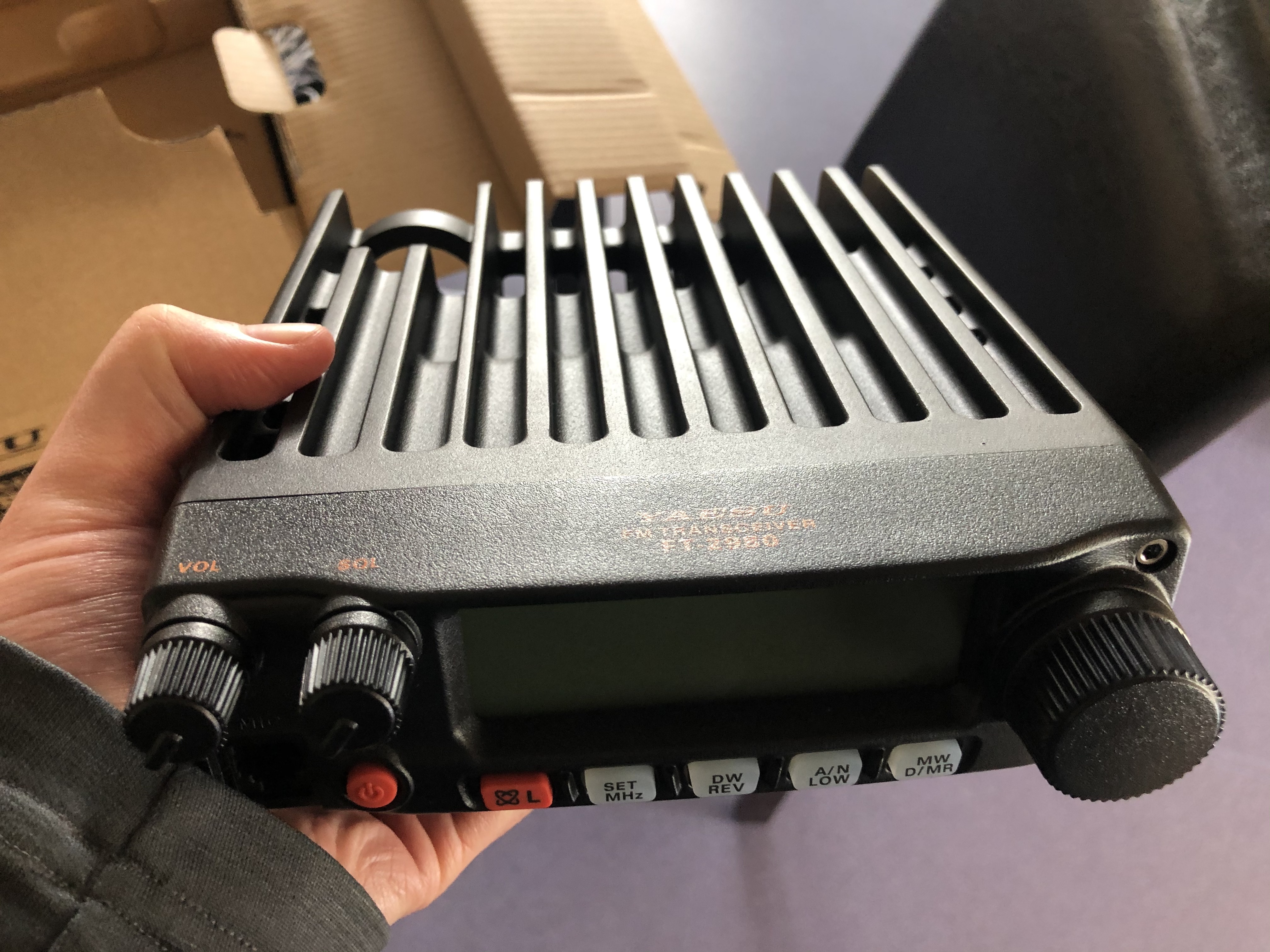
Yaesu FT-2980R, 80% of which is apparently heat sink
Antenna Build
I didn’t yet have an antenna for the 2m band. Fortunately, Bradley VK3LIT was ready to help me out. We followed his instructions and shortly had a working 2m dipole.
I then sourced a 3m long, 50mm diameter PVC pipe from Bunnings that allowed me to get some height.
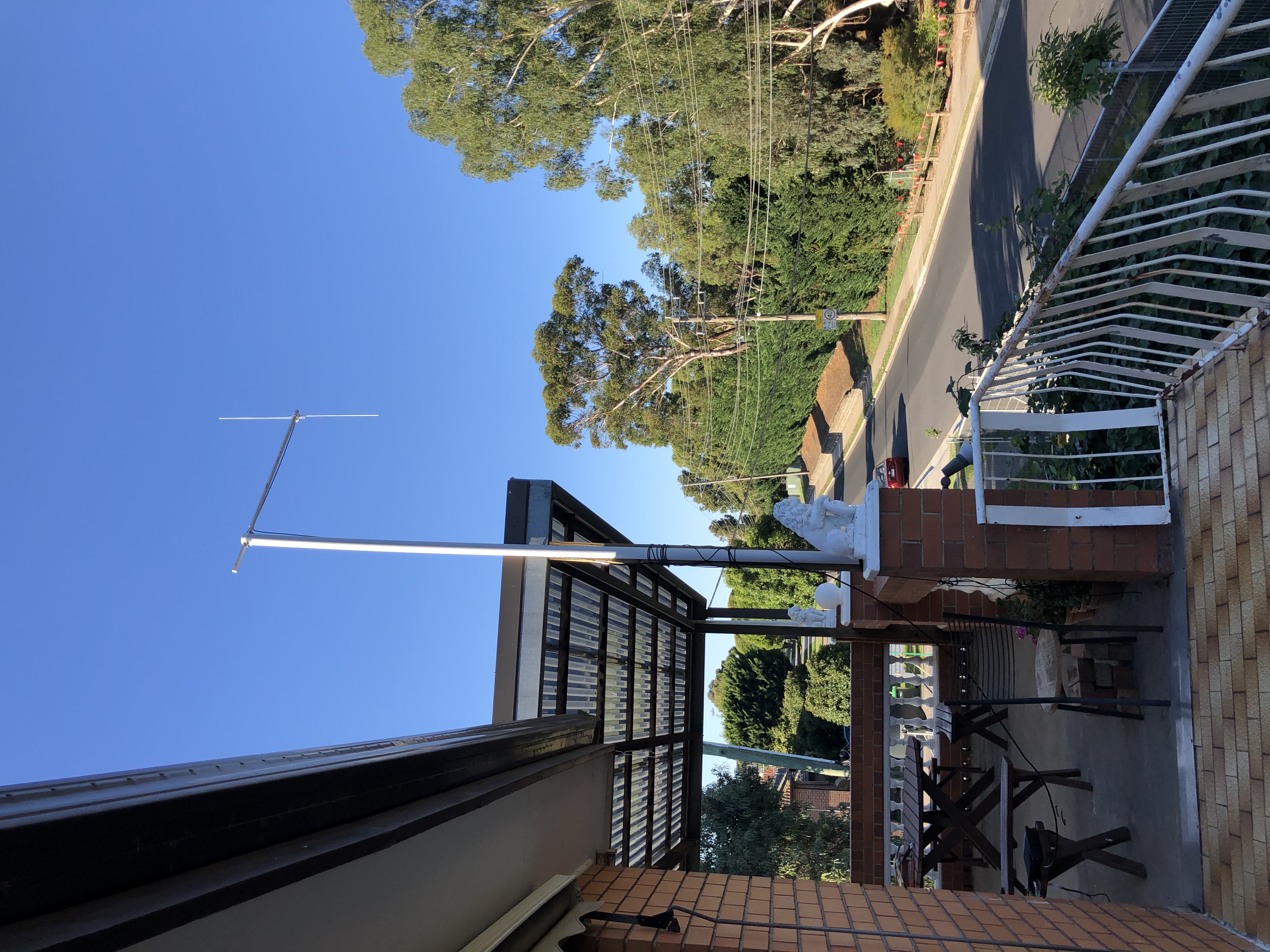
Antenna Installed
I discovered however that on windy days, the antenna was liable to rotate (roll) in its mount at the top of the vertical post. Luckily 3D material is very easily drilled, and I placed a 90mm bolt through to arrest this.
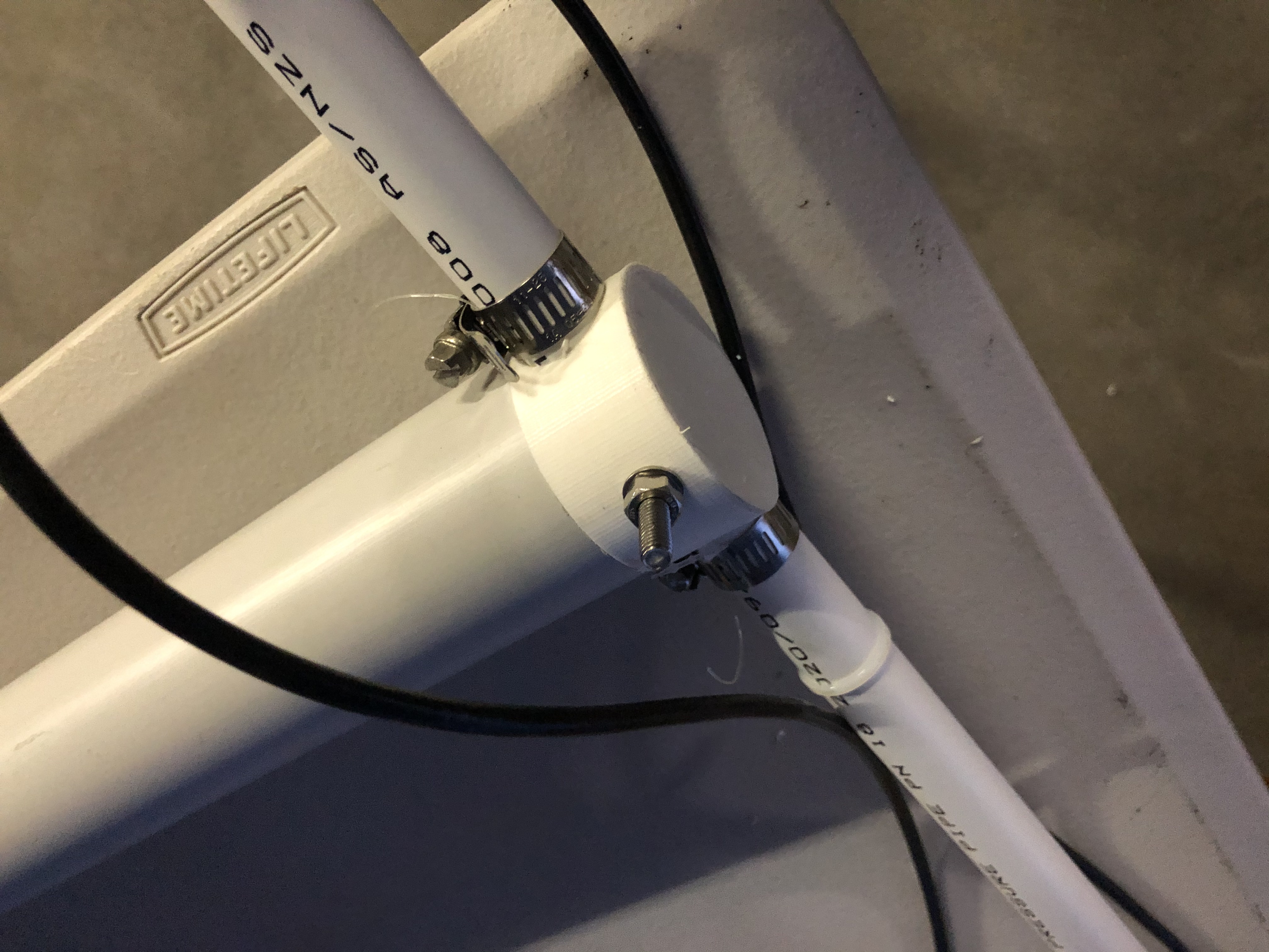
One bolt solves our problems
Cable Build
It was necessary to build two cables: the output of the radio to the intput of the Raspberry Pi, and a franken-cable from the Raspberry Pi to the microphone input plug on the radio.
Radio Output
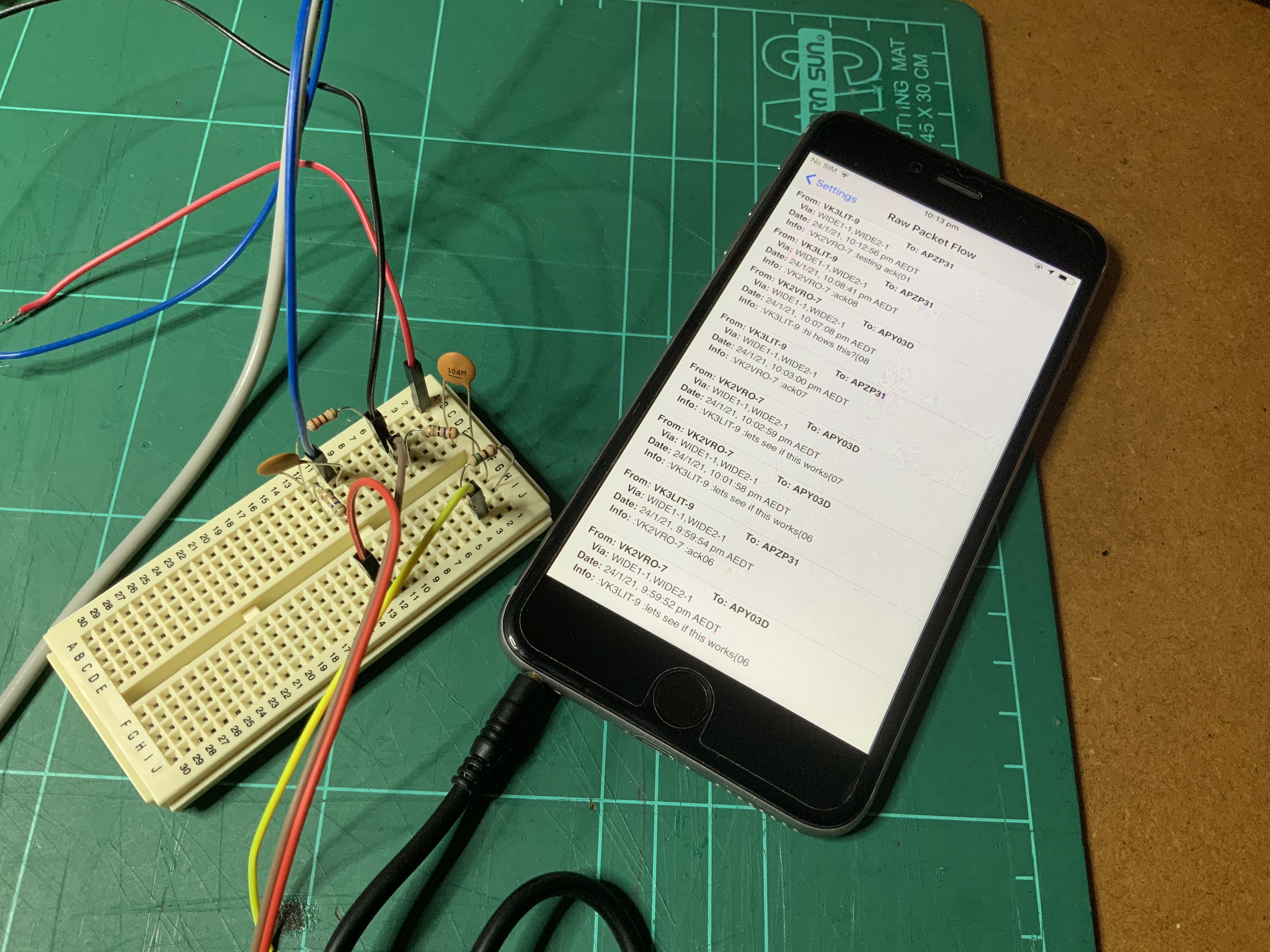
Bradley's first line-level circuit proof-of-concept, connected from his iPhone to his radio for transmission (not pictured)
The radio output signal would be packets that need to be decoded by the software running on the Raspberry Pi. This is conceptually relatively straightforward — you have a signal (LOUD) that you want to be quieter. You can use a voltage dividider circuit to get what you need. It is also adviseable to insert a small-valued capacitor into the input lead, to ensure that no DC-bias exists on the output.
To get the right values for the voltage divider, we started with 100kΩ resistor, and a variable potentiometer. Plugging the output into the radio software (Direwolf, below) to determine if the signal was picked up, we found the right value for the second resistor.
We did also use the assistance of an oscilloscope, to understand the starting position of the output of the radio, and the likely values we’d be looking at. The input required by the Raspberry Pi is line level, and the voltage divider network’s purpose is to get there.
Because the Raspberry Pi does not have a ‘line-in’, this solution required the use of a USB audio adapter, and configuring this via the command line use of aplay. The system needed to have default levels for the soundcard configured before the radio would successfully work. We turned the sound levels up all of the way, until they turned red (approximately 65%).
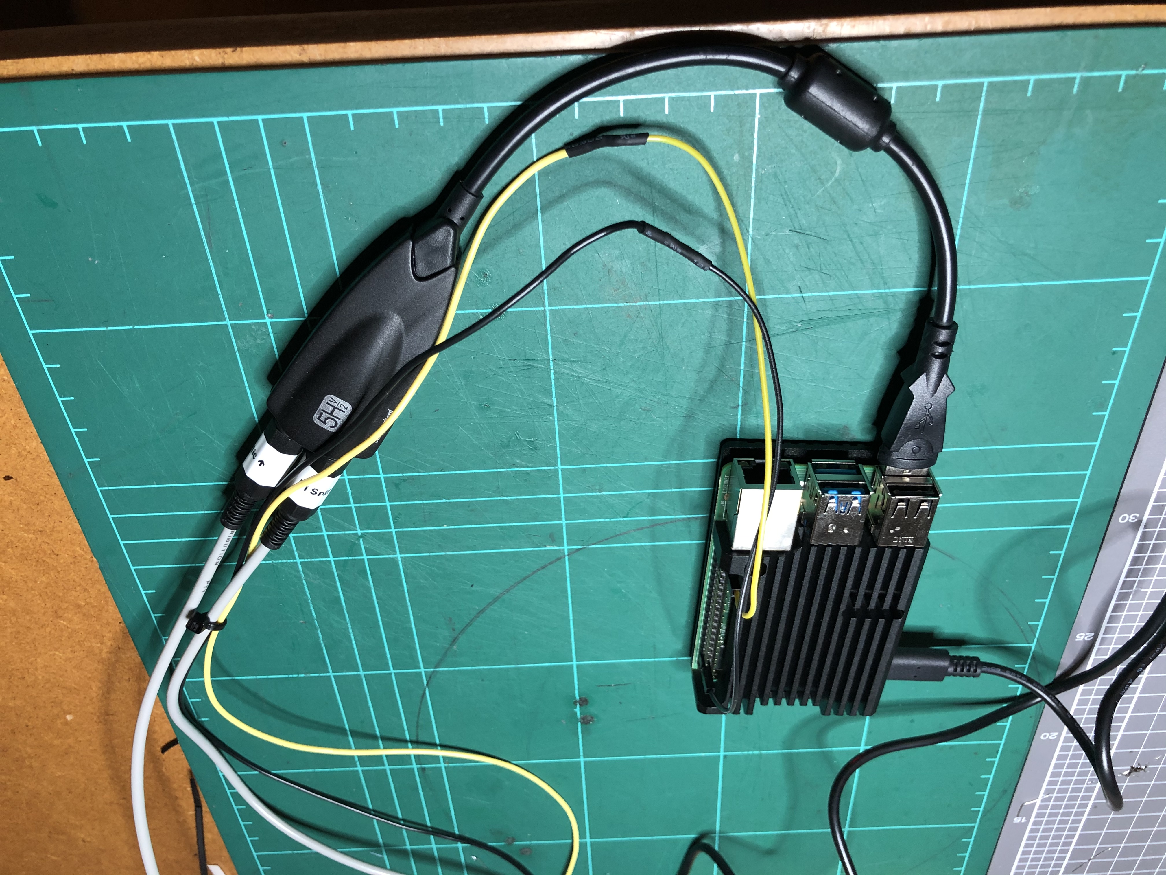
Complete audio solution
Radio Input
The radio input presented more of a challenge. To activate the push-to-talk (PTT), a separate line is required to tell the radio to go into transmit mode. In the picture above, Bradley was relying on the radio’s VOX option, however this is not a best-practice. And we were not about to go to all of this trouble to end up with a flaky solution.
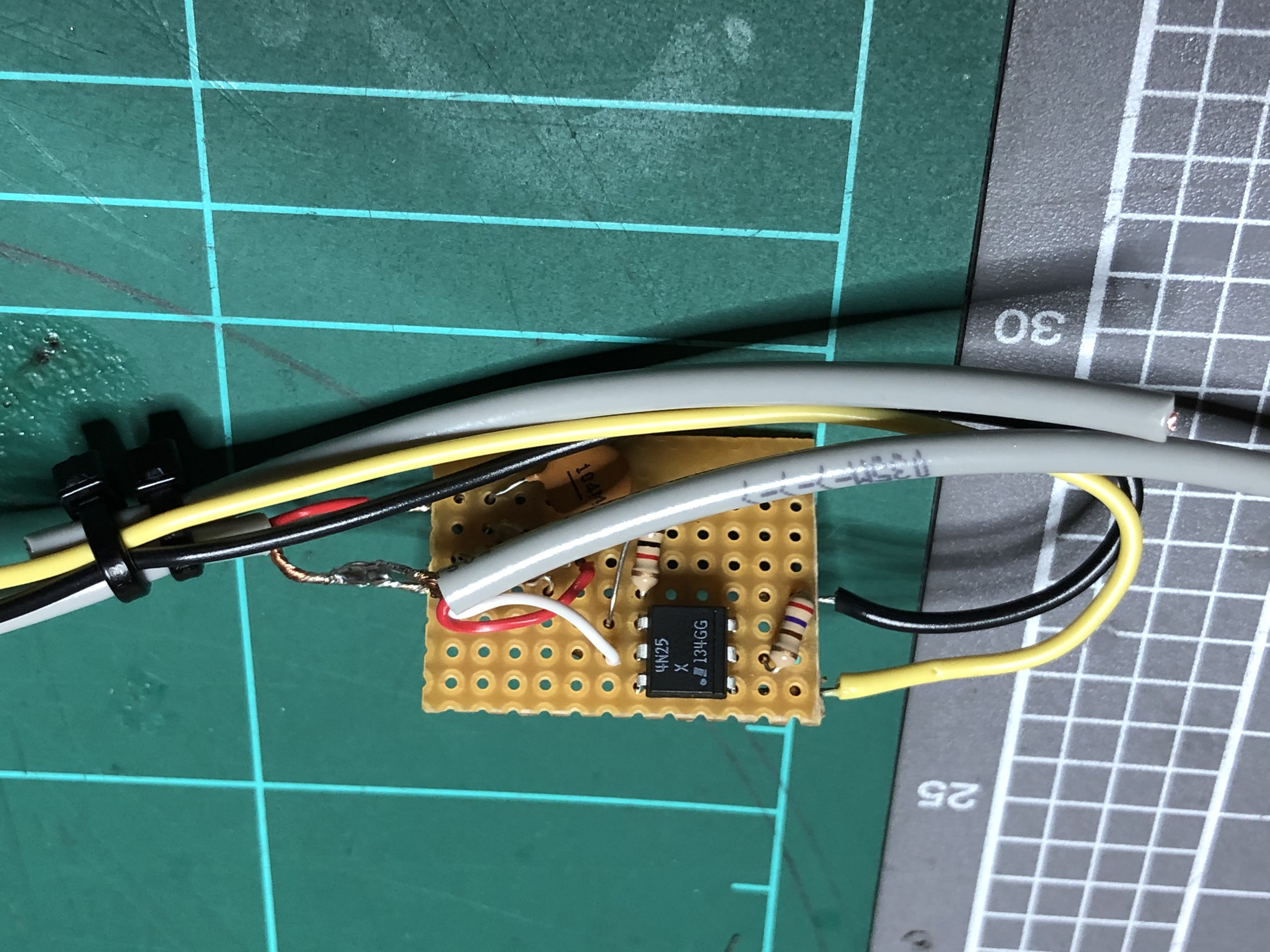
The soldered circuit
Fortunately, Direwolf allows the user to nominate any of the Raspberry Pi’s output pins as a ‘PTT pin’. To separate the different voltage levels, Bradley inventively suggested the use of an opto-coupler. This allows the Raspberry Pi to drive an LED, the sensing of which optically induces a current in the connected line to drive the PTT line.
The PTT line is ‘activated’ when driven low (0V). I was uneasy with shorting the line completed, so placed a 1kΩ resistor in series. This pulls the line low, but allows me to sleep more easily at night.
APRS Server Software
Looking at the available options, Direwolf seemed to be the standard and best choice for software. The user guide has a wealth of information and I recommend reading it through before starting.
I recommend running Direwolf in a tmux session. This allows direwolf to continue running without anything being connected. When starting the server, I use the following commands (omit the $, that shows it is a shell prompt):
$ tmux new-session -t direwolfto create a newtmuxsession nameddirewolf.- Inside the new
tmuxsession you’re now in, run$ direwolf -t 0 -pto startdirewolf
To close the session (but keep it running), I type crtl-b then d, which disconnects me. Alternatively, you can just close the terminal window.
To reconnect, at the shell prompt, type $ tmux attach-session -t direwolf -d. The -d will disconnect other sessions connected to the direwolf session. Do this if you want the screen to fill your terminal window.
Addendum: 2021-06-13
Now that I’ve had some time to run this station, I’ve found that my setup commands have turned into these:
$ tmux new-session -t direwolf$ direwolf -t 0 -p 2>&1 | tee >(logger -ie -t direwolf)
This second command redirects error output (STDERR) to standard output (STDOUT), and sends this along to tee. tee is a way of doing two things with input — showing it, and piping it elsewhere. In this case, we are showing it, and sending it to logger, which is the syslog agent on the Raspberry Pi. I have the Raspberry Pi configured to send all syslog messages to my syslog server. This is outside the scope of this write-up, however to point you in the right direction, I have added the following to /etc/rsyslog.conf on the Raspberry Pi:
*.* @<IP_ADDRESS_OF_SYSLOG_SERVER>:514
Finished Product
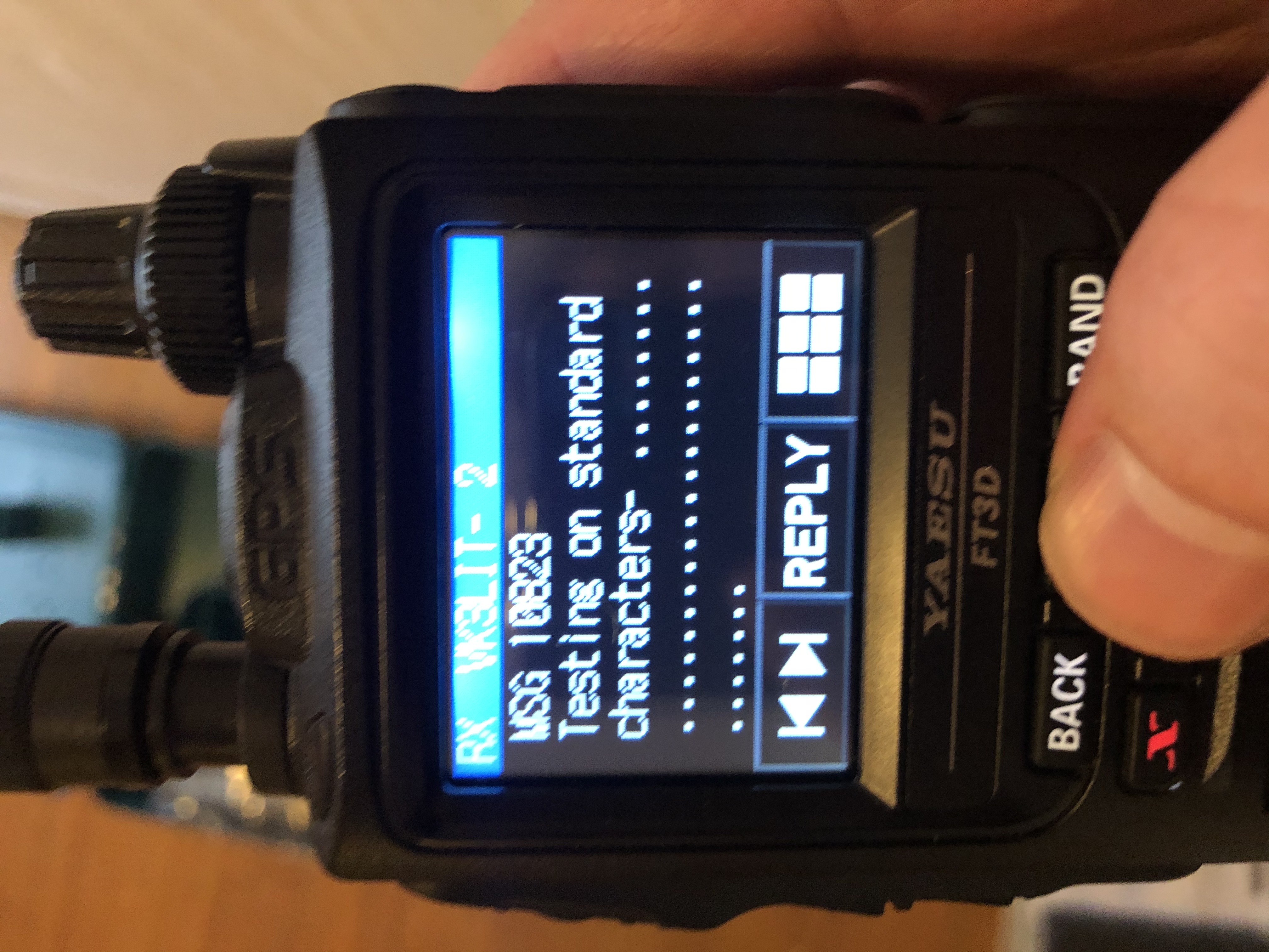
A successfully received message

Sample server output
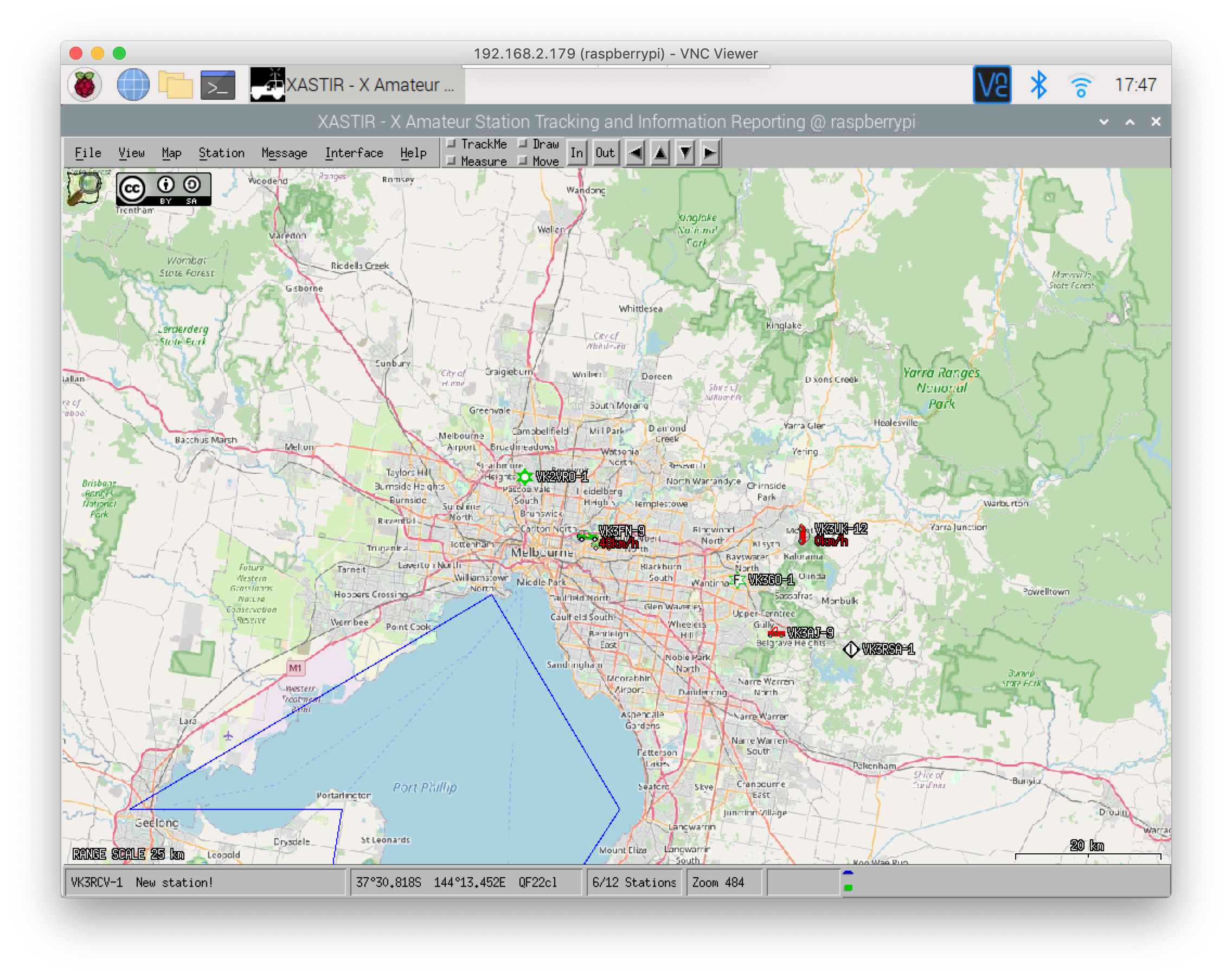
Sample Xastir output, listening to outputs of Direwolf
Next Steps
VK3LIT and I both want to work next on expanding our packet radio abilities, into a more permanent messaging ability. This may look something like a BBS functionality.
I’m quite happy that I’ve managed to significantly improve the coverage of APRS in the nothern suburbs of Melbourne for just the cost of a radio, and a few evening mucking around with circuits. My thanks to VK3LIT for the use of his impressive shack, parts, and expertise.